43 electric motor diagram with labels
General Electric Motor Wiring Diagram - Database 3. Three-inch guideline. It's always better to have too much wire than not enough. There are wire extensions available if you finish up cutting them short, but the wiring will work better if it is intact. Since a rule of thumb, you'll want to have wiring that is very long to extend 3 inches outside of the electrical box. Electrical Technology | All About Electrical & Electronics Engineering Electrical Technology | All About Electrical & Electronics Engineering
Electrical Drawings and Schematics Overview - TestGuy The logical functions in these diagrams are represented by their respective symbols whereas the blocks are used to represent the complex logic circuit. The blocks in a logic diagram are labeled for a better understanding without knowing the internal structure and are connected by lines which represent input and outputs for the binary signals.

Electric motor diagram with labels
Electric Car Diagram - Car Construction Car Anatomy and Repair, Electric car, Engine, How a car Works, Construction. The active reference to source is obligatory if you use materials of a site Car Anatomy 852 shares PDF Typical Electrical Drawing Symbols and Conventions. Basics 6 7.2 kV 3-Line Diagram : Basics 7 4.16 kV 3-Line Diagram : Basics 8 AOV Elementary & Block Diagram : Basics 9 4.16 kV Pump Schematic : Basics 10 480 V Pump Schematic : Basics 11 MOV Schematic (with Block included) Basics 12 12-/208 VAC Panel Diagram : Basics 13 Valve Limit Switch Legend : Basics 14 AOV Schematic (with Block included) Beginner's Guide - How to Read Electrical Schematics Part 3: Recognizing Connection and Lines in Electrical Schematics. Understanding the representation of symbols and components is just the primary stage in reading electrical schematics. Next, you need to identify how the symbols are connected and how to figure out their connections. 1. Nets are lines that will show how components are connected. 2.
Electric motor diagram with labels. Electrical Diagrams and Schematics - Inst Tools Types of Electrical Diagrams or Schematics There are three ways to show electrical circuits. They are wiring, schematic, and pictorial diagrams. The two most commonly used are the wiring diagram and the schematic diagram. The uses of these two types of diagrams are compared in Table 1. Electrical Technology | All About Electrical & Electronics Engineering A block diagram is a type of electrical drawing that represents the principle components of a complex system in the form of blocks interconnected by lines that represent their relation. It is the simplest form of electrical drawing as it only highlights the function of each component and provides the flow of process in the system. What is an Electric Motor? with the Help of a Labelled Diagram ... An electric motor is a device that converts electrical energy into mechanical energy. Diagram: Electric motor Working of an electric motor: An electric motor works on the principle of magnetic effect of electric current. What details a motor nameplate shows and how to use them The nameplate for a two-pole 15 kW motor may have the following important data: Data #1 The motor has three phases and is for a mains supply with a frequency of 50 Hz. Data #2 The rated output of the motor is 15 kW, i.e. the motor is able to supply a shaft output of at least 15 kW if connected to the mains supply as indicated.
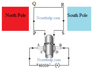
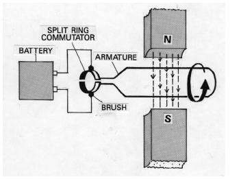
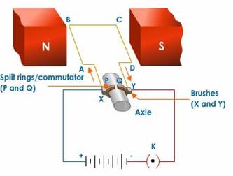
The picture shows a basic diagram of an electric motor. Which labels ... The picture shows a basic diagram of an electric motor. Which labels best complete the diagram? X: Brush Y: Armature Z: Commutator X: Commutator Y: Brush Z: Armature X: Armature Y: Commutator Z: Brush X: Armature Y: Brush Z: Commutator Expert-verified answer SerenaBochenek Types of electric vehicles with labeled battery and motor outline diagram Types of electric vehicles with labeled battery and motor outline diagram. Illustration about comparison, auto, chassis, outline, isolated, technology, fossil, diagram - 217894989 ... Types of electric vehicles with labeled battery and motor outline diagram. Educational scheme with hybrid, plug-in and electricity car power supply vector ... Electric Motor - Principle, Working, Diagram - teachoo Electric Motor consists of Rectangular Coil of Wire ABCD A strong horseshoe magnet (or 2 different magnets ) - If we take 2 magnets, North Pole of first magnet faces South Pole of Other Magnet, as shown in figure... The coil is placed perpendicular to the magnet as shown in figure The ends of coil are connected to split rings - P & Q Single Phase Electric Motor Wiring Tutorial: Baldor, WEG, Leeson In this video, Jamie shows you how to read a wiring diagram and the basics of hooking up an electric air compressor motor. These tips can be used on most ele...
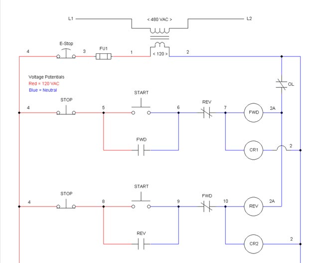
Explain the construction and working of the following. Draw a neat ... Draw a neat diagram and label it. Electric motor . Maharashtra State Board SSC (Marathi Semi-English) 10th Standard [इयत्ता १० वी] Question Papers 172. Textbook Solutions 10056. MCQ Online Tests 30. Important Solutions 1991. Question Bank Solutions 7383. Parts of Motor, Working of Electric Motor & Uses - BYJUS Take two bar magnets and keep the poles facing each other with a small space in between. Now, take a small length of a conducting wire and make a loop. Keep this loop in between the space between the magnets such that it is still within the sphere of influence of the magnets. Now for the last bit. Connect the ends of the loop to battery terminals. Basic wiring for motor control - Technical data guide | EEP Figure 1 - Typical Wiring Diagram Line diagrams show circuits of the operation of the controller Line diagrams, also called " schematic " or " elementary " diagrams, show the circuits which form the basic operation of the controller. They do not indicate the physical relationships of the various components in the controller. PDF Electrical Symbols and Line Diagrams - University of Florida A line (ladder) diagram is a diagram that shows the logic of an electrical circuit or system using standard symbols. A line diagram is used to show the relationship between circuits and their components but not the actual location of the components. Line diagrams provide a fast, easy understanding of the connections and use of components.

Patent US4593163 - Electric motors and method of manufacturing and operating same - Google Patents
PDF Understanding Electric Motor Nameplates Figure 2 is a view of the underside of an electric motor. The letters are NEMA standard letters and the actual dimensions for general purpose motors are shown in Table 1. The diameter of the bolt hole of the motor mounting bracket is letter H. The diameter is 1/32 of an in. larger than the bolt used for mounting.
Draw a labelled diagram of an electric motor, principle and worki
Electric Motor Symbols Electric motors are electromechanical devices whose function is to transform electrical energy into mechanical energy through electromagnetic interactions. There are other engines ( generators) that produce electricity by exploiting the mechanical energy, such as alternators and dynamos. It may interest you...

Patent US1068531 - Electric motor. - Google Patents
Motor Connection Diagrams - Electric Motor Warehouse Single Phase Terminal Markings Identified By Color: (NEMA Standards) 1-Blue 5-Black P1-No color assigned. 2-White 6-No color assigned P2-Brown. 3-Orange 7-No color assigned. 4-Yellow 8-Red. Three Phase Connections: Part Winding Start: 6 Leads NEMA Nomenclature: WYE or Delta Connected.

Automotive Diagnostic Tools: Animated Diagrams: Electrical Current Flow
Question 11 Draw a labelled diagram of an electric motor ... - Byju's Principle: It works on the principle of the magnetic effect of current. A current-carrying coil rotates in a magnetic field. Working: When a current is allowed to flow through the coil MNST by closing the switch, the coil starts rotating anti-clockwise. This happens because a downward force acts on length MN and at the same time, an upward force acts on length ST.

Wiring a 9 lead motor to Drum Switch
Draw a labeled diagram of an electric motor. Explain its principle and ... Working of electric motor: As shown in the diagram, when a current is passed through the coil PQRS the coil starts rotating anti clockwise because a downward force acts on length PQ and at the same time an upward force acts on RS. Therefore, the coil rotates in anti clockwise direction.

draw a neat labelled diagram of simple electric motor - Brainly.in
7 Parts Of Simple Electric Motor And Function - AutoExpose The trunk, the magnet is placed on a pivot with the circuit in such a way that it can produce rotary motion when these two components interact. Electric Motor main Components 1. Stator Coil 2. Rotor Coil 3. Main Shaft 4. Brush 5. Bearing 6. Drive Pulley 7. Motor Housing Simple Motor Parts and their function 1. Stator / Armature Coil

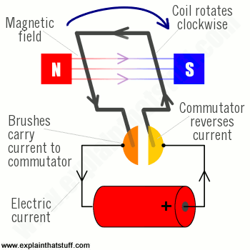
How do electric motors work? - Explain that Stuff Animation: How a universal motor works: The electricity supply powers both the magnetic field and the rotating coil. With a DC supply, a universal motor works just like a conventional DC one, as above. With an AC supply, both the magnetic field and coil current change direction every time the supply current reverses.
ELECTRICAL ENGINEERING AND PROJECTS: November 2014
Electric Motor Nameplate Details Explained | Electric Motor ... The nameplate shown in Figure 1 indicates the electric motor is rated 1 HP. With a service factor of 1.15, the motor can be overloaded up to 1.15 horsepower. If the motor is operated in the service factor range continuously, it will cause a reduction in motor speed and efficiency, and an increase in the motor's operating temperature.

ELECTRICAL ENGINEERING AND PROJECTS: The electric motor:
Electric Motor Diagrams - Mr. Electrician's Home Page A Split Phase Capacitor Start Electric Motor may be defined as a form of split-phase motor having a capacitor connected in series with the auxiliary winding. The auxiliary circuit is opened by the centrifugal switch when the motor reaches 70 to 80 percent of synchronous speed. Also known as a capacitor-start, induction-run motor.

Engineering Photos,Videos and Articels (Engineering Search Engine): Diagram of a wind turbine
How To Read An Electric Motor Nameplate Usually labeled as HP or kW, this is the measure of the motors ability to deliver the torque required for the load at a rated speed. hp = 0.746 x kW; conversely, kW =1.34 x hp. Time Rating or duty (DUTY). This designation specifies the length of time that the motor can safely carry its nameplate rating.
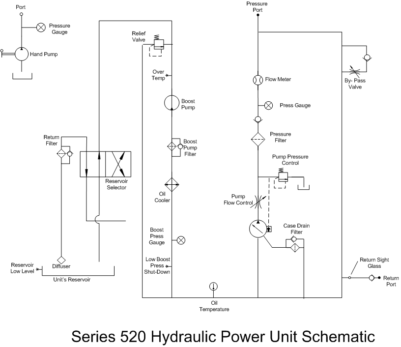
Series 520 HPU - Super Duty Hydraulic Power Unit
Beginner's Guide - How to Read Electrical Schematics Part 3: Recognizing Connection and Lines in Electrical Schematics. Understanding the representation of symbols and components is just the primary stage in reading electrical schematics. Next, you need to identify how the symbols are connected and how to figure out their connections. 1. Nets are lines that will show how components are connected. 2.
Honda ES6500 A GENERATOR, JPN, VIN# GX360-1000001 TO GX360-1017635 Parts Diagram for RADIATOR FAN
PDF Typical Electrical Drawing Symbols and Conventions. Basics 6 7.2 kV 3-Line Diagram : Basics 7 4.16 kV 3-Line Diagram : Basics 8 AOV Elementary & Block Diagram : Basics 9 4.16 kV Pump Schematic : Basics 10 480 V Pump Schematic : Basics 11 MOV Schematic (with Block included) Basics 12 12-/208 VAC Panel Diagram : Basics 13 Valve Limit Switch Legend : Basics 14 AOV Schematic (with Block included)

Electric motor diagram - YouTube
Electric Car Diagram - Car Construction Car Anatomy and Repair, Electric car, Engine, How a car Works, Construction. The active reference to source is obligatory if you use materials of a site Car Anatomy 852 shares
EZ Schematic Diagram Software
Explain Electric Motor
AC induction motors | How AC motors work - Explain that Stuff

Patent US6271609 - Programmable electric motor and method of assembly - Google Patents
Post a Comment for "43 electric motor diagram with labels"